CNC ATC (Automatic Tool Changer) Hardware Setup for the Avid CNC EX Controller / Centroid
These are directions on how to setup an automatic tool changer (ATC) with an Avid CNC using Centroid’s Acorn controller and CNC12 software, the “EX Controller”. It is mainly geared towards people who are using a CNC Depot ATC spindle, such as the S30 / S30C / RM15 / RM40 / RM70 (et), but also works with other spindles, such as the HITECO QD-1F that I use. It is heavily based on the initial directions by Eric Schimelpfenig from Avid CNC. I also just looked at the board and figured out what things seemed to be doing what operations. For Mach 4 goto my Mach 4 ATC Hardware Setup.
WARNING: These are just my observations!! Make these changes at your own risk. I do not support modifying your stuff unless you really know what you are doing! I make no warranty that these are correct.
Air Compressor: You’ll need air to run the tool changes, and having dry air is important. Review my prior guide about setting up air: ATC Hardware Setup with Mach 4.
Drawbar Wiring
The drawbar opens by applying compressed air to the spindle, and closes when the air is removed. The Centroid/Acorn controller will power a drawbar relay; that relay closes a circuit and gives power to a solenoid which provides the compressed air (output B below) and opens the drawbar to release a tool. When the controller stops powering the relay the drawbar no longer has air and closes, clamping a tool.
Here’s a diagram showing how it works; note that I should figure out how to add an additional relay for “spindle lock” that is controlled by the VFD to disable the “drawbar signal”:
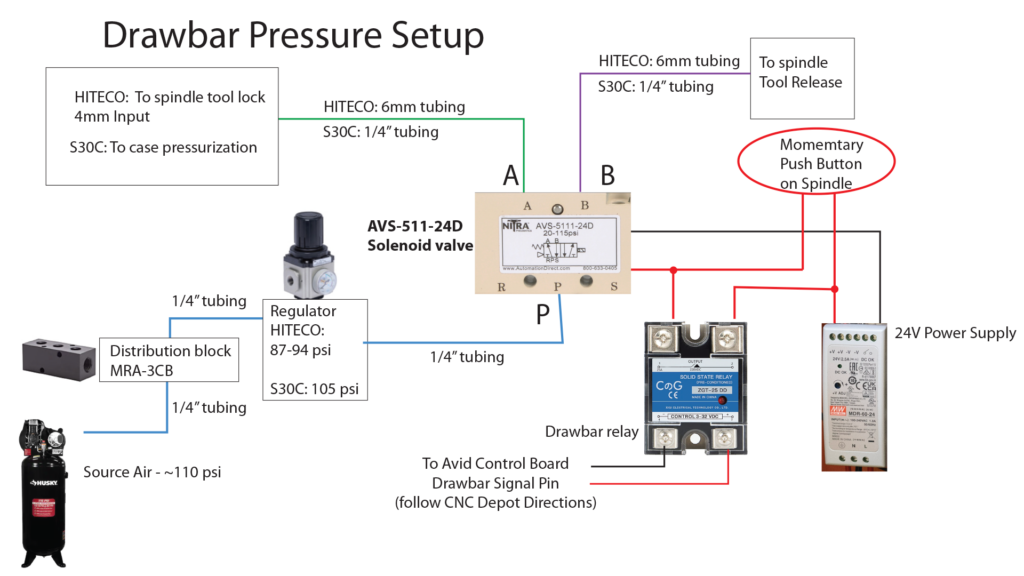
NOTE: I really should add in another “interlock” relay to cut power to the drawbar relay when the spindle is running. That will avoid you accidentally opening the drawbar while the machine is running. This would be controlled by the VFD, and require VFD programming.
Relays: On some relays, such as the one shown above, need to have polarity correct, which means the red power wire needs to be on the + side of the control relay, and the negative ground wire needs to be on the – side.
Locate the drawbar relay in your spindle box. I believe CNC Depot has two varieties:
A. A separate gray wiring going directly from the relay into the Avid CNC Control Box with contains a red and black wire. This is what I have; red is the positive wire, and black is the ground.
B. Others may have used some auxiliary wires from the 14-pin spindle wire to connect to the relay, specifically the orange/black wire going to the “plus” side of the relay, and a black/white wire will be the shared “ground” going to the “minus” side of the relay. If you have this style, inside the Avid control box where the 14-pin spindle wire goes to, you’ll find a zip-tied bundle of unused wires; you’ll need to cut the zip tie and pull out the black/white wire (it is unhooked) and get the orange and black wire from the torch+ hookup on the board:
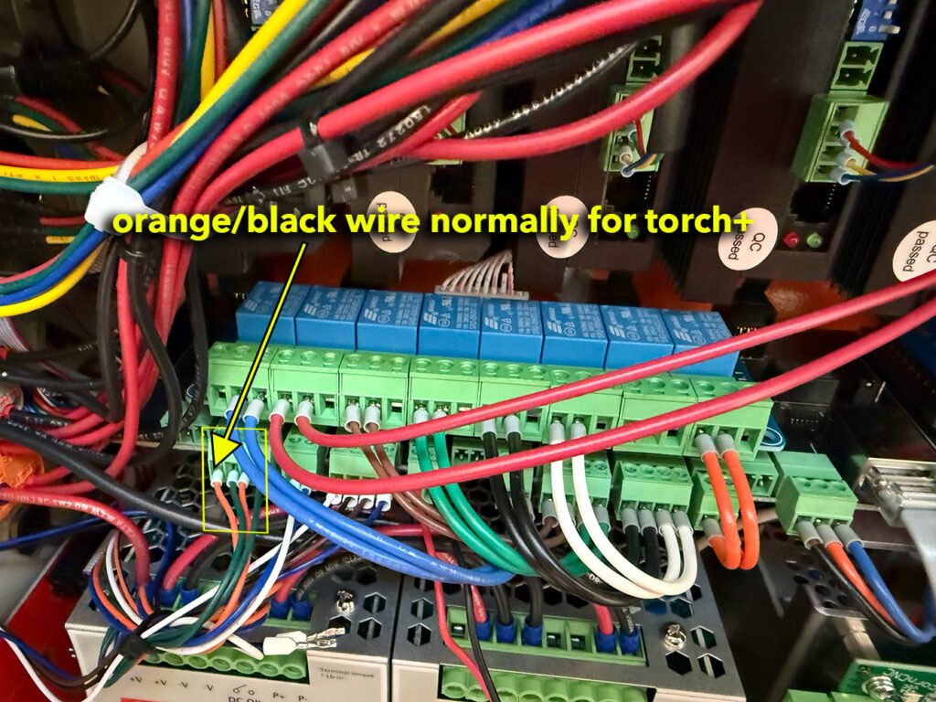
NOTE: I’m going to discuss one way to do this, but you could also choose to wire things directly to the Acorn board, which might actually be easier.
We’ll be overriding the “plasma torch” relay #6 inside the Avid Control Box to control the drawbar.
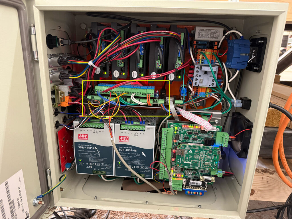
Here’s an overview of the control box with the area we are focusing on highlighted in yellow:
The board with all the little blue boxes is the relay board. Underneath it is another board, Avid’s CRP5210-01E interconnect board.
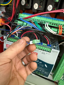
I didn’t realize this for a while, and it might help you, but if you look underneath the CRP5210-01E board you can see the names of each pin. It’s kind of hard to see, and a wiring diagram would be nice to have. I couldn’t get a good picture, but here is one:
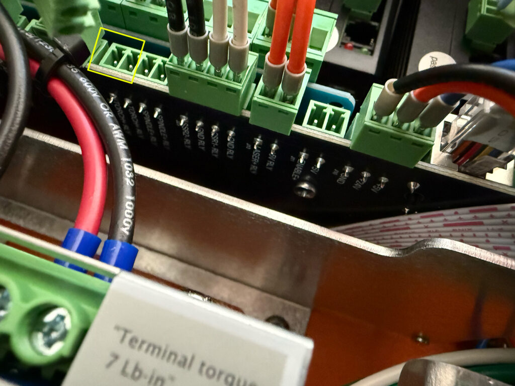
In the area highlighted above, I unplugged the connector which had the two brown wires going to the relay board and two green wires. We’ll be removing the brown wires.
NOTE: the green terminal block connectors (the things the wires go into) can be unplugged to allow you to more easily add and remove wires. I used needle nose pliers and gently pulled them out.
NOTE: I believe Avid can provide a CNC Depot ATC wiring kit that includes additional wires and green terminal plugs. I didn’t have that. If you have the servo box, you will need it!
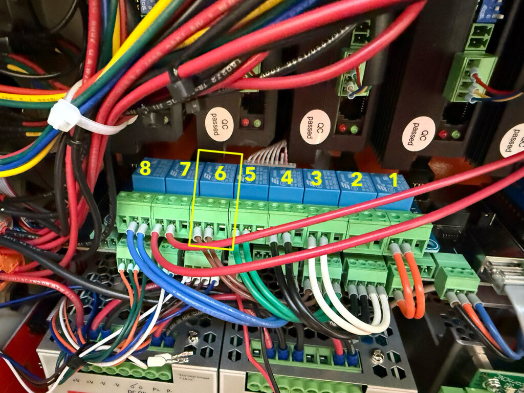
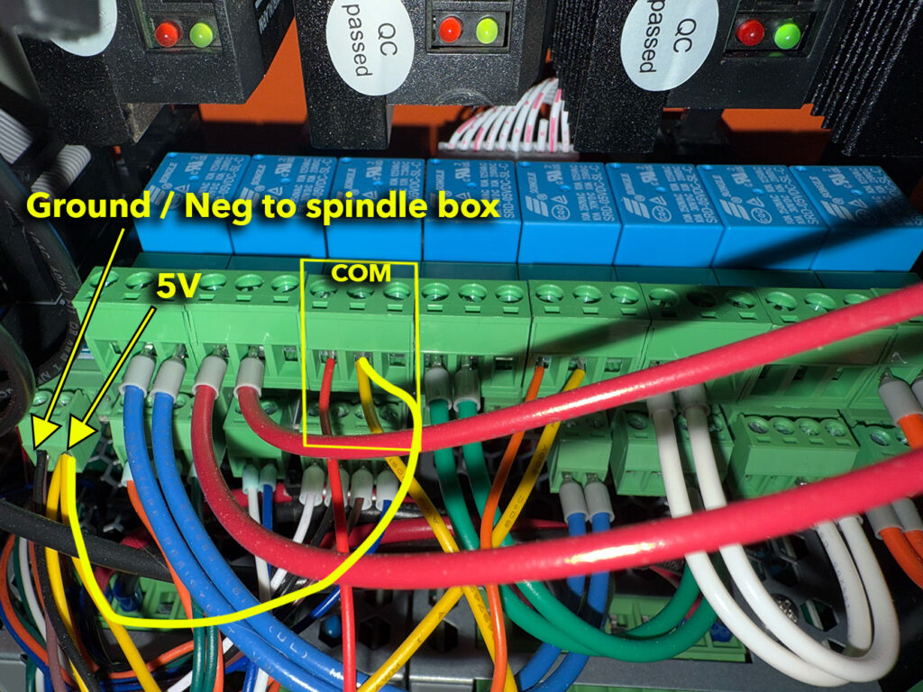
The relays are numbered from 1 to 8 going from right to left, as shown above. Relay 6, for Plasma Torch, is highlighted in yellow.
Remove the brown wires shown above from relay 6 and the CRP5210-01E interconnect board below it.
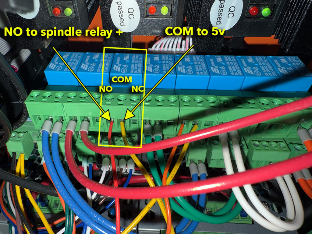
Each relay (the blue boxes) have three terminals. From left to right we have: NO=”Normally Open”, COM=”Common”, NC = “Normally Closed”, which you can see written on the board when you pull out the green terminal.
Put the “drawbar relay positive wire” into NO (Normally Open) spot shown above. In my photo above it is a thin red wire, but yours may be a different color (as I mentioned earlier), such as orange/black.
Next we need to provide 5 volts to the COM (Common), which in the photo above is the thin yellow wire going into COM.
Caution: the next steps are specific to the Stepper Motor CRP5210-01E interconnect board because the pins were open. The servo motor board has to have power from a different location (coming next).
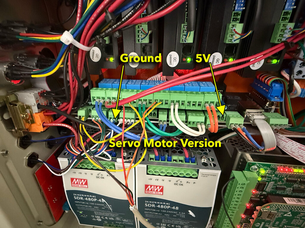
When I looked under my CRP5210-01E interconnect board, the furthest left pins were open, and the leftmost one was ground and the next one was 5, as shown above.
STEPPER MOTOR VERSION: Connect the 5v to COM on relay 6, as shown above. I used a yellow wire (because I had it around). If you have another relay for your spindle “fan/case pressurization“, add a second yellow wire into the 5v for use in a short bit. I didn’t have a green plug in connector, so took the one off the board that was used for the “air pressure check”, shown to the right, which has a blue and back wire. I just followed the wires from the input area to figure out what they were. I’ll add air check in down below.
Connect the Drawbar Relay’s Ground Wire (either black or black/white, as determined at the top) to the Ground/Negative terminal shown in the above picture. If you have a second relay for “fan/case pressurization” wire it’s ground into this same location. Some CNC Depot boxes only have one ground, the black/white wire, and it is shared.
SERVO MOTOR VERSION: I don’t have this version, but looking at other people’s pictures and Eric’s wiring these are the places to attach the 5V access and Gnd pins, which will likely require additional green terminal blocks (get them from Avid or Amazon) placed per below; my ground has the Spindle Fault Ground hooked up to here. I assume it is open for the servo motor version…
At this point the drawbar relay is wired up. Here’s how current flows: 5 volts constantly flows into the NO side of Relay 6, but it is “normally open” and no circuit is completed. A “drawbar open” signal powers Relay 6; this provides 5v to the COM side of the relay, which travels to the positive side of the drawbar relay , through the rely to the negative side, which then travels to the Ground/Neg.
This is probably all the S30C spindles need, as it doesn’t have a fan and you can skip to the CNC12 Software Setup <LINK>. Case pressurization is always on, but you re-do it to wire it on a relay, as shown below.
Spindle Fan/Case Pressurization
Newer CNC Depot RM series spindles, the Hiteco QD-1F, and others, require something to turn on the spindle fan and case pressurization. It’s usually easiest to have one input that does both of these things at the same time with one relay in the spindle box, and I’ll refer to it as the “fan/case relay”. Some setups may simply turn these on when the VFD is turned on, and that works well. I wanted to control it in code, for better or for worse.
Here’s the generic wiring diagram I made to keep it straight in my head:
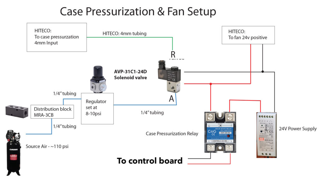
As before, your spindle box may have an extra wire to do the case pressurization (this is what I have), or it may use the green/black wire from the 14-pin spindle box connector, which is located ned to the orange/black wire:
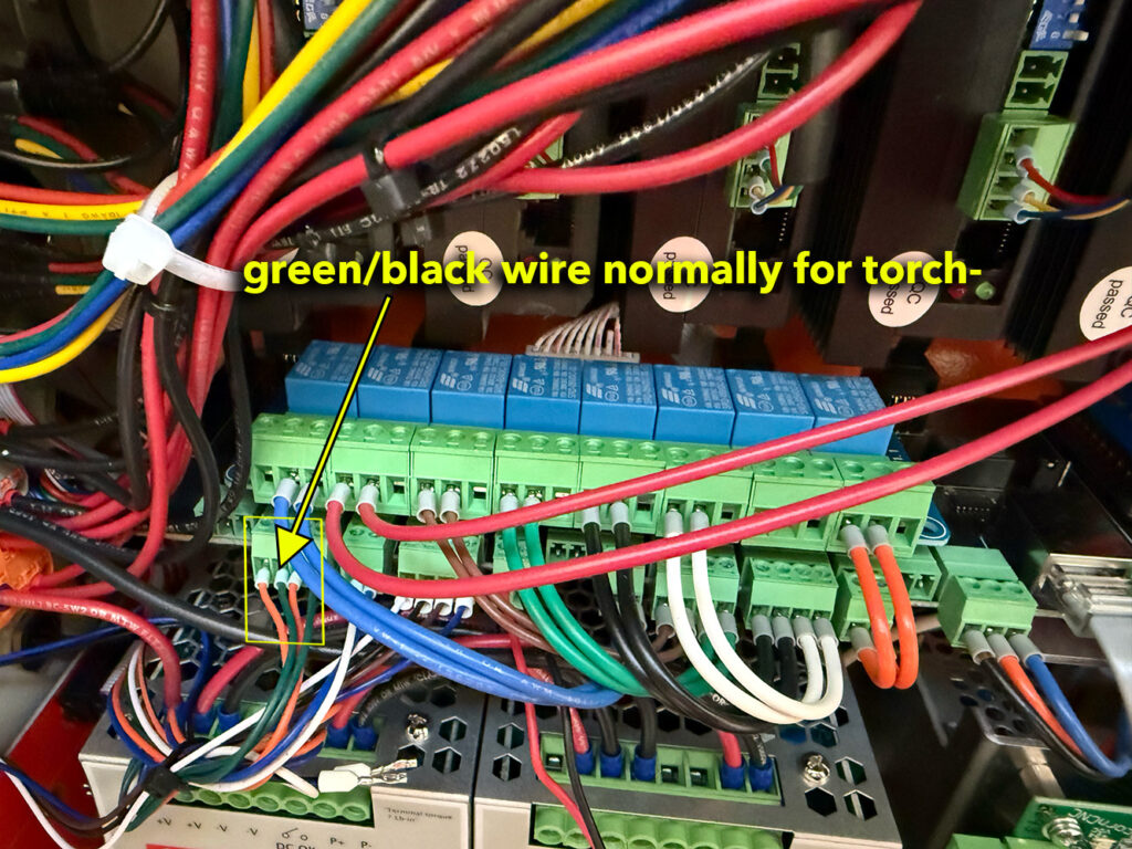
Avid provides two “User” relays that they call “Relay 1” and “Relay 2“. We’ll overwrite “Relay 2” to control the fan/case relay.
Now the possibly confusing part: Relay 2 is just a name for end users, and on the Avid Relay Board it is “Relay #4” from the right, shown below.
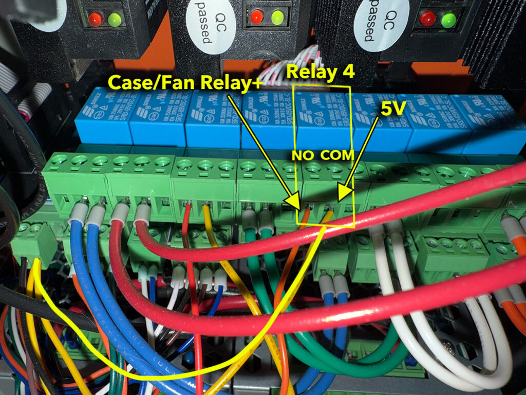
Disconnect the black wires going from Relay #4 on the Avid Control Board to the Avid interconnect board below it. Take the extra 5v power source, as we talked about earlier, and add connect it to the COM of the relay #4. The NO side then does to the Case/Fan Relay + in your spindle box; if you have the 14-pin wire used, that is the green/black wire you took off of Torch-.
Inside of Avid’s setup wizard you can set the Relay #2 to turn on with the job and off with the job. This turns on your air/case pressurization when the machine starts, and off when it is done. I customized this a little more to turn off when ever the spindle turns off by modifying my m5 macro.
Air Pressure Sensor
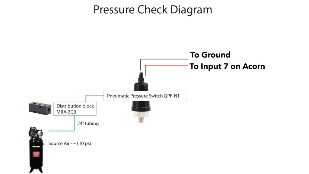
You don’t want to try a tool change unless your air compressor is turned on. Avid’s laser also requires air pressure, and we can piggy back off that sensor’s input. There are two easy ways to wire this; either you can look under the board and find the “Air Pressure” and “Gnd” pins, or you can connect directly to the corresponding pins on the Acorn board. I did the latter.
If you look on the Acorn PCB board you can see the pin names to the right of the pin connections. The top one is COM (Ground). 3rd up from the bottom is Input 7.
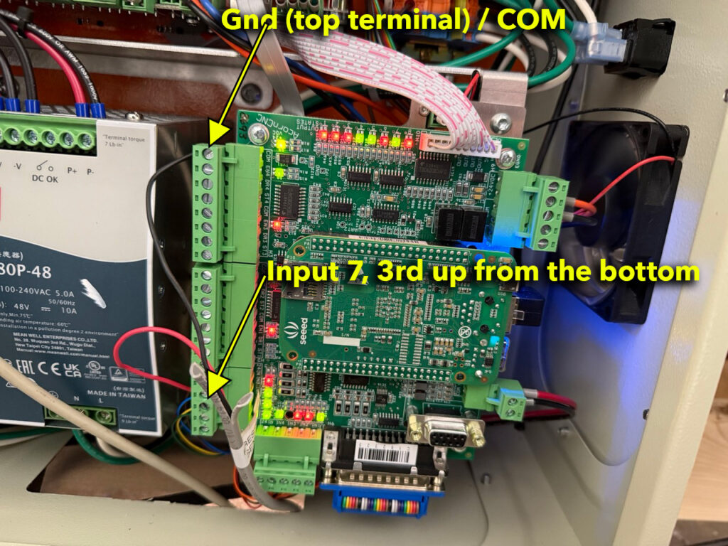
I put the + side of the air pressure sensor into input 7, and the – side of the air pressure sensor to the “Gnd/COM”. If you flip the wires it probably doesn’t matter; I don’t think the air sensor is directional. Acorn sends out 5v on Input 7 and when air is on, it completes the circuit going to ground. So, you want to wire the air sensor on the “normally open” side, and ensure it closes when it has air. This is for safety; when air is on the circuit will have power. If a wire is accidentally pulled out, the circuit will be open, and the system will see “no air”.
Avid’s Wizard has an option to turn on the air pressure check, and you’ll need to turn it on! There are also parameters you can directly set in case you don’t want to use the wizard. Definitely test it; make sure that pulling a wire from your sensor will cause it to prompt for air input.
VFD Updates
Avid’s setup now requires VFD parameters to be updated. Check their instructions here for your VFD brand: https://www.avidcnc.com/support/instructions/electronics/ex/manual/ex_vfd_update/
I have a DuraPulse GS10 from Automation Direct, which wasn’t listed.
Read Chapter 3 for how to change parameters: https://cdn.automationdirect.com/static/manuals/gs10m/gs10usermanual.html
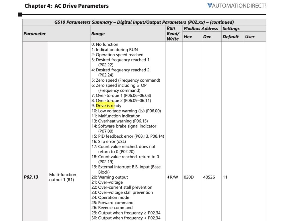
I set parameter P02.13 from 11 (Malfunction) to 9 (Drive is Ready):
Centroid Setup
Once you got all this going you have to make one change to Centroid’s Inputs.
- Start CNC12
- Click Utility Menu
- Click Acorn Wizard // it starts the Wizard
In Avid’s wizard, assuming you have an air input check, be sure to set “What to do when air pressure is low” to “Warn me” or “Stop Machine”:
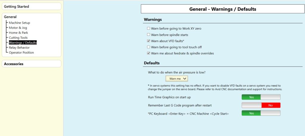
I prefer it set to “Warn me”, which loops until you turn on the air when it is needed.
- Click the bottom left button to go to advanced mode from Avid CNC mode
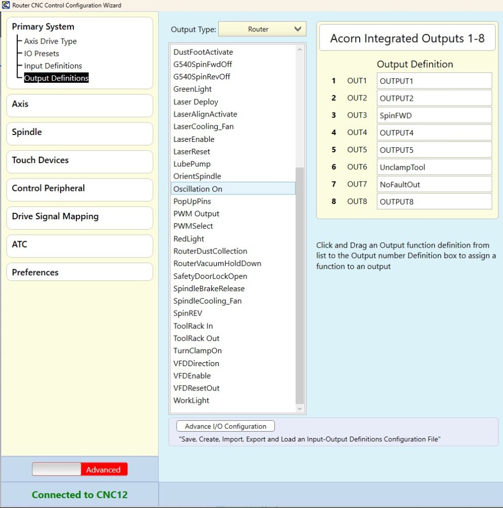
- Click on Primary System, Output Definitions
- Find UnclampTool in the list
- Drag and drop it to OUTPUT6, shown below.
- Hit Write Settings
- Save everything…restart the controller and CNC12
Next step: Centroid ATC Software Setup for Avid CNC.

