CNC ATC (Automatic Tool Changer) Software Setup for Centroid CNC12 & Avid CNC
Last updated: Jan 20, 2025
Prerequisites
- Avid CNC with the EX Controller / Centroid CNC 12.
- I can support other machines, but currently I rely on their tool touch plate macros
- For Mach 4, visit: Avid CNC ATC with Mach 4
- Machine has the touch plate and spoilboard calibrated, although I cover how to do this in the video
Features / Goals
- Full ATC support for rack style tool pockets / holes / forks
- Any tool number in any pocket number
- Automatic tool height measurement
- Tools not in the rack: user prompts to install and remove when needed
- Tool Library Management
- Save & restore the position when a tool change happens
- Easy to use User Interface
TODO:
- Laser support is reported to work! I don’t have one, and can’t test it.
- Better metric support: It *should* work fine if you put metric values, but the defaults are in inches.
- Disable some UI parts when a job is running
- Always on top option?
- Elapsed runtime, time left (for repeat jobs), time left estimate
Hardware Installation / Modifications
Read the guide I wrote: CNC ATC (Automatic Tool Changer) Hardware Setup for the Avid CNC EX Controller / Centroid
Basics:
- The drawbar relay is wired to the Acorn OUTPUT6 as UnclampTool. (Use Avid’s Wizard in Advanced Mode).
- Relay 2 is overridden to operate the spindle fan and case pressurization relay.
- Relay 2 is set to start/stop with the job (Use Avid’s Wizard)
Software Installation
- Backup your CNC12 “profile” by using Avid’s Profile Manager to copy your current setup, that way you can switch back to it if something bad happens. You could also manually copy the profile directory at “C:\Program Files (x86)\Avid CNC\AvidCNC“ Centroid Profile Manager\Profiles\User\<profile name>”.
- Download the latest release from: https://github.com/corbinstreehouse/Centroid-ATC-ToolRackSetup/releases
- Expand Assets
- Manual Install: Download the .zip file
- Quit CNC12, and, if you are upgrading, be sure to quit ToolRackSetup.exe
- Manual Install:
- Copy the “cncm” folder in the zip file to your C:\ drive, and hit yes when prompted to overwrite files. Here’s what files are included
- Avid’s VCP: resources\vcp\skins\avid_router.vcp overwrites Avid’s existing “Virtual Control Panel” to add more buttons.
- Avid Macros: AvidMacros\mantoolmeasure.mac and AvidMacros\mtc.mac are fixed to work with an ATC. If you upgrade from Avid these will get overwritten.
- ToolRackSetup.exe (etc): The setup app, which can only be run from the C:\CNCM directory, and will get errors if launched from outside of that directory.
- CorbinsWorkshop: Contains the new macros.
- mfunc3/5/6/15/16: Modifications of Avid’s macros. Everything is minimal except M6, which calls my main macro in CorbinsWorkshop for the tool change.
- Copy the “cncm” folder in the zip file to your C:\ drive, and hit yes when prompted to overwrite files. Here’s what files are included
ATC Tool Pocket Setup
1. Start CNC12 and Home your machine.
2. Click “ATC Tools” to launch c:\CNCM\ToolRackSetup.exe
- NOTE: CNC12 must be running while the app is being used!
- Be sure to exit the app if you quit CNC12 (otherwise it’ll give errors).
- The User Interface has changed a bit, but the concepts below will always apply.
3. The screen shot below shows the application with everything setup.
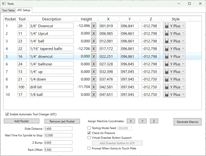
4. Check “Enable Automatic Tool Changer (ATC)“.
5. Click “Add Pocket” to add the first pocket.
6. Jog machine’s X and Y position to your first pocket. See Finding Tool Pocket Positions.
- You can leave the app running and switch back and forth from CNC12 and ToolRackSetup
7. In ToolRackSetup, select the row containing the pocket.
8. Click the “X” and “Y” buttons next to “Assign Machine Coordinates” to take the current machine position and assign it to the selected row’s tool pocket.
9. For “Z”, and initial testing, I recommend jogging your Z axis up to the top (Machine Z 0), and then down a few inches (Machine -2″). Assign this value for Z by clicking the Z button. After you do some testing you can come back and set Z to the proper value based on Finding Tool Pocket Positions.
10. Pick a “Style” for the pocket that matches your fork orientation, assuming you are standing in front of the machine.
11. Click “Add Pocket“; this will duplicate the last pocket’s values to the next pocket, as most pockets are just variations in the X or Y.
12. Repeat the process to add all your pockets. For testing, you might want to add just two.
13. Setup the additional options:
- Slide Distance: How far the machine will slide when inserting and removing a tool. This has to be far enough to clear your tool forks, but also far enough for wide bits (ie: 2″ surfacing) to clear the rack. You can put a tool in and see how far you have to jog to get it completely out of the pocket, noting the start and ending distances and doing some basic math. 1.4″ is probably the minimum recommended distance, but you might want it to slide 2″ for large bits. This value is ignored for “Holes”. Default is 1.4″.
- Wait Time for Spindle To Stop: This is the time, in seconds, your spindle takes to stop spinning before a tool can be put in the rack. I record the “spindle stop” time in m5 and do a wait above the rack for it to spin down. The VFD can provide this information (spinning or not), but most systems won’t have it wired up. Default is 12 seconds.
- Z Bump: Some spindles have “push out” when fetching a tool and clamping. Z bump is added to the pocket location and the clamp will happen at this location *above* the pocket, and then it will move down and slide out. This only happens when clamping. If it happens when unclamping then I’ll have to modify some code (let me know) to make it happen there. Default value is 0.005″ which is basically negligible on my HITECO; CNC Depot Spindle users may want it to be larger, such as 0.100″. Set it to 0 and it will not do anything.
- Rack Offset: The tool change will target “rack offset” distance from the pocket when getting a tool and putting one back before it goes over the pocket position. This is needed for people with short z axis travel (8″) where a long bit might stick down and hit the top of other tool holders in the rack. It would really only happen at extreme angles, but it was reported to me as an issue so I added this in. You can set it to 0 to disable it, but it doesn’t hurt to have it in. The default value is 5.5″.
- Testing Mode Feed: If checked, all the macros will be written out with the given feed rate in order to test things. Turn this on when testing! Use a feed rate of 200 (IPM) or less to be more cautious (ie: 100 or 150).
- Check Air Pressure: If checked, the air pressure will be checked before a tool change. This requires you to set it up like how Avid has it for their laser, which I’ll discuss in Hardware setup. This option control’s Avid’s parameter.
- Virtual Drawbar Button Support: Check only if you don’t have a physical button on your spindle to open and close the drawbar. If checked, the macros will prompt the user when a manual tool change is happening and the user needs to open and close the drawbar.
- Add Drawbar Button to VCP: This button will (and remove) a virtual drawbar button to the VCP panel. It edits the current VCP skin you have setup in options and adds the “drawbar” button.
- Prompt When Going To Touch Plate: Check if you want a prompt before a tool has the height automatically measured. This is useful if you have to remove a dust boot. This option control’s Avid’s parameter for this feature.
14. Click “Generate Macros” to write out the macros for your tool pocket positions. These are saved in C:\CNCM\CorbinsWorkshop\Generated\.
- The software should keep track of when you have to re-generate macros or not. Re-generation at anytime shouldn’t cause issues. Changing some things, like the tool in a pocket, don’t require re-generation.
15. Setup what tools are in what pocket. Just type the number in the tool column and hit enter. Enter 0 to “clear” a pocket. For testing, just put tool 1 in pocket 1 and tool 2 in pocket 2.
- Changes are stored in CNCM’s tool table, and are written as soon as they are changed.
- Changing the description will update the tool table; characters limited to 19.
16. TESTING
- Be prepared to hit Cycle Stop on your pendant, or e-stop in case something bad happens!
- Test with no tools in the spindle, and at a “high” z-value and “Testing Mode Feed” checked.
- Click “Fetch Tool”, enter “1” and click Cycle Start.
- Observe that the fetch will move in the directions you are expecting and that you hear the drawbar opening at the right times.
- After a “virtual” fetch happens, it will try to measure the tool; click Cycle Stop to cancel the measurement, or manually trip the touch off plate (just be sure to remove that tool height!).
- Click “Fetch Tool”, enter “2” and click Cycle Start
- Observe how tool #1 will be put back, and make sure the moves are what you are expecting.
- Observe how tool #2 is fetched.
- Cycle Stop to avoid measuring tool 2.
- If directions look right, go back and set your Z-position for the pockets.
- Click Generate Macros to generate macros with the new pocket positions.
- Repeat the test in the same way, but without any tools in the rack.
- If it looks right, put in your tools and give it a real test!
- After ensuring everything is right, uncheck “Testing Mode Feed” and re-generate the macros. This will run everything at rapid speed.
Virtual Control Panel (VCP) Enhancements
There are four (or five) new buttons to Avid’s VCP Skin:
Set Tool: If you manually remove a tool you need to tell the system about it. Put in 0 if you don’t have any tool in the spindle. This also activate’s that tool’s height (G43).
Put Back: Puts the tool back in the rack, or if the tool has no pocket it will go to the touch plate location and prompt to remove it. All this does is “M6 T0” and “G43 H0”.
Fetch Tool: Puts back the current tool (if non-0) and fetches the tool requested. If a tool isn’t in the rack, it will go to the touch plate location and ask the user to put it in before continuing. It also actives the tool’s height (G43). This does “M6 Txx” and “G43 Txx”. The latest version now shows a drop down window for tools.
Draw Bar: If you enable the virtual draw bar, and click “Add Virtual Drawbar Button to VCP”, you will get this button that prompts and manually opens the drawbar; waits for the user to do something (insert/remove bit), and then closes it. I only recommend using this if you do not have a physical button on your spindle! It can be dangerous if you accidentally click it when your machine is running.
Moving to a new Profile?
After installing the files, you can copy CNCM\CorbinsWorkshop/ToolPocketPositions.xml to the new profile. I also recommend copying your existing tool table files (CNCM\cncm.tl and CNCM\cncm.ol).
Run the ATC Tools program and you should be able to re-enable the ATC with all the previous pocket positions and tools setup.
Bit Changes and Tool Heights
Tool heights are saved in the CNC12 tool library.
If you remove a bit from a tool holder you must reset the Tool Height to 0. The Height column has an “X” button next to it to easily set it to 0:

You can also do this in the native tool library UI. When the tool is requested again it will measure the height.
Post Processor Notes
A tool change involves two commands: “M6 Txx” and “G43 Hxx”, where xx is the tool number requested. M6 is what changes the tool and G43 activates the tool height offset. They should always be paired together. Some of Avid’s post processors don’t do this, so I made the M6 tool change always call G43 for the requested tool. This should make my macros work with any of the standard Avid Post Processors.
Known Issues
The CNC12 UI will show whatever tool # was requested right away. If you cancel the tool change (cycle stop, e-stop, etc), the UI will still show that same number. Behind the scenes, I should still have the actual tool # still in the spindle safely recorded, and stuff should still work. But to be safe, you can always do a “Set Tool” and assign the number that is actually in the spindle.
Param 06 and Param 160 are CNC12’s native ATC support, but requires PLC logic. They should be set to 0. The system seems to work fine when Param 06 is set to 1, as I assign the right PLC parameter, but the UI will keep defaulting to show the tool from the last job at certain times, which can’t figure out how to fix. Setting Param 160 to non-0 will cause errors when you try to put tool 0 in the spindle or a temporary tool that doesn’t have a pocket/bin (which I support!).
Finding Tool Pocket Positions / Tool Stations
This is based on Jason Parker’s Guide. Thanks Jason!
First, ensure your machine is homed! Set your jog speed to something slow, and take it easy to avoid crashes. If you don’t have a laptop, then use a pendant to jog your machine, or a wireless keyboard.
Finding the tool station locations is not difficult. There are two methods of finding the tool fork locations. Method 1 is more precise but takes more time and has more steps to the process. While method 2 is faster but not as precise. However, method 2 arrives at a similar result. Both processes will be described and the steps outline for both. Choose what is best for the system and the level of precision desired.
Method 1: Double Tool Holder Higher Precision (Figure 25)
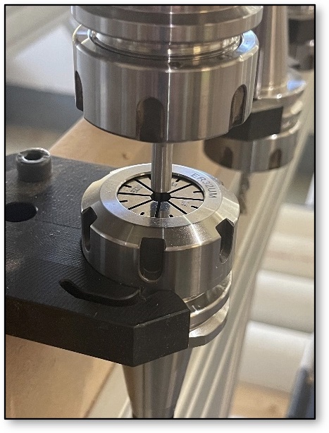
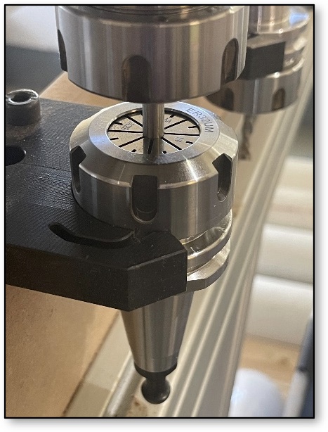
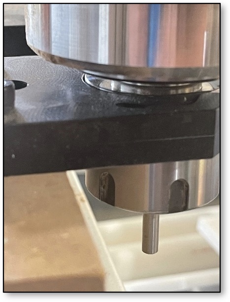
This requires two tool holders, both with the same size collets. Tool holder one will have a precision steel dowel installed and be loaded into the spindle. You can also use an upside down bit. Tool holder two will have a loose collet and is placed upside down in the tool station fork. The spindle is jogged over to the inverted tool holder and the dowel is jogged down into the collet. This finds the X/Y plane values for the station. The Z value is found by driving the tool holder into the fork after the inverted holder is removed from the station. This method gives a much more precise X/Y value. This means there is less potential for damage from the tool holder taped rubbing or scratching the inside walls of the spindle when either lowering or lifting during tool exchanges.
Method 2: Single Tool Holder Lower Precision (Figure 26)
This method is faster than method 1 and arguably less precise, however, the results can be good if care and attention to detail are taken while executing the process. The method uses a single empty tool holder installed into the spindle. Carefully drive the holder into the fork paying attention to the deflection of the two arms of the fork. The arms should deflect outward at the same time and distance. Jog the tool holder into the fork until it is fully rested in the folk. While the tool holder is parked in the fork, the X, Y, and Z values can be found.
Method 2 is considered less precise than method 1 because the tool holder could be under or overdriven into the holder in X, Y, and/or Z. When the drawbar is then released, the fork will exert a force to center the holder in the fork. When the spindle raises or lowers this difference could scratch the taper inside the spindle or on the tool holder, neither is desirable on precision machined surfaces. Additionally, if misaligned going in or out of the fork it could damage the fork or cause the fork to not hold the tool correctly causing it to fall possibly damaging a tool.
Method 1: Double Tool Holder Higher Precision
Below is an outline of the process for using the double tool holder method of finding fork locations. This is a step-by-step process.
- Home the machine
- Setup
- Tool holder 1
- Install precision steel dowel (or inverted endmill) into tool holder, allow a minimum of 0.75” (19mm) stick-out from the collet
- Install tool holder into the spindle
- Tool holder 2
- Install the same sized collet as tool holder 1. When installing the collet nut, it should hold the collet such that the steel dowel slides into the collet with light friction
- Install holder in the station fork with the collet facing the spindle
- Tool holder 1
- Process
- Set the Z to a safe distance above the inverted collet in the tool fork
- Jog roughly over the tool holder
- Slowly Z down toward the collet empty collet of the inverted holder
- Make X, Y, and Z adjustments until the steel dowel in the tool slides into the empty collet of the tool holder 2. Watch for any deflection of tool holder 2, this indicates the holders are not aligned and more adjustments are needed.
- Once aligned, click the <– Assign button to assign the X and Y position for this pocket.
- Raise the Z to clear the dowel from holder 2
- Remove tool holder 2 from the fork
- Jog in the direction of the fork opening such that the tool holder can be safely lowered and slid into the fork (do not use the Z at this time)
- Try and jog only in the one axis to move in front of the fork opening.
- Lower the Z until the groove of the tool holder is aligned with the lip in the center of the tool station fork. The flat at the bottom of the ISO30 taper should align with the top surface of the tool station fork.
- Adjust only the Z and the axis needed to slide the tool holder into the station fork.
- The X and Y values should match those found in part 4e of this section.
- If the tool holder appears fully seated, click the <– Assign button for the Z value on the pocket.
- Jog the tool holder out and clear of the fork.
- Install tool holder 2 into the next station and repeat for the next pocket position.
Method 2: Single Tool Holder Lower Precision
Below is an outline of the process for using a single tool holder to locate the tool station fork locations. This is a step-by-step process.
- Home the machine
- Setup
- Install an empty tool holder into the spindle
- Decrease the jog rate to a very slow rate. The tool holder is going to be jogged directly into the holder so a slow jog rate will increase the precision and decrease the cause of damage in the event the tool is jogged in the incorrect direction.
- Process
- Lower the Z to approximately level with the tool station fork
- Jog roughly to the first station fork opening
- The flat at the bottom of the tool holder taper should be roughly on the same plane as the tool station fork top surface
- Carefully jog the spindle to move the tool holder into the fork
- Adjust the X and Y such that when the tool holder moves into the fork both arms deflect at the same time and for the same amount.
- Adjust the Z to ensure the lip at the center of the fork slides into the groove in the tool holder and that the flat at the bottom of the tool holder at the bottom of the taper is level with the top surface of the tool station fork. See figure 25.
- Continue to jog the took into the fork opening until the holder is fully seated in the fork, this is slightly subjective. Do not overdrive or underdrive the tool holder into the fork as doing so will cause the tool holder to shift in the fork when the spindle releases it. Misalignment has the potential to damage the tool holder taper or mating surface inside the spindle during a tool change process. Misalignment may also cause premature wear of the tool holder, spindle, and/or tool station forks.
- Once the tool holder is seated correctly in the fork, click the <– Assign button for the X, Y and Z position of the tool pocket.
- Carefully jog the holder out of the station fork
- Repeat for all the pockets

