Borneman Timber Frame Layout Guide – 3D Printed (Free STL Download)
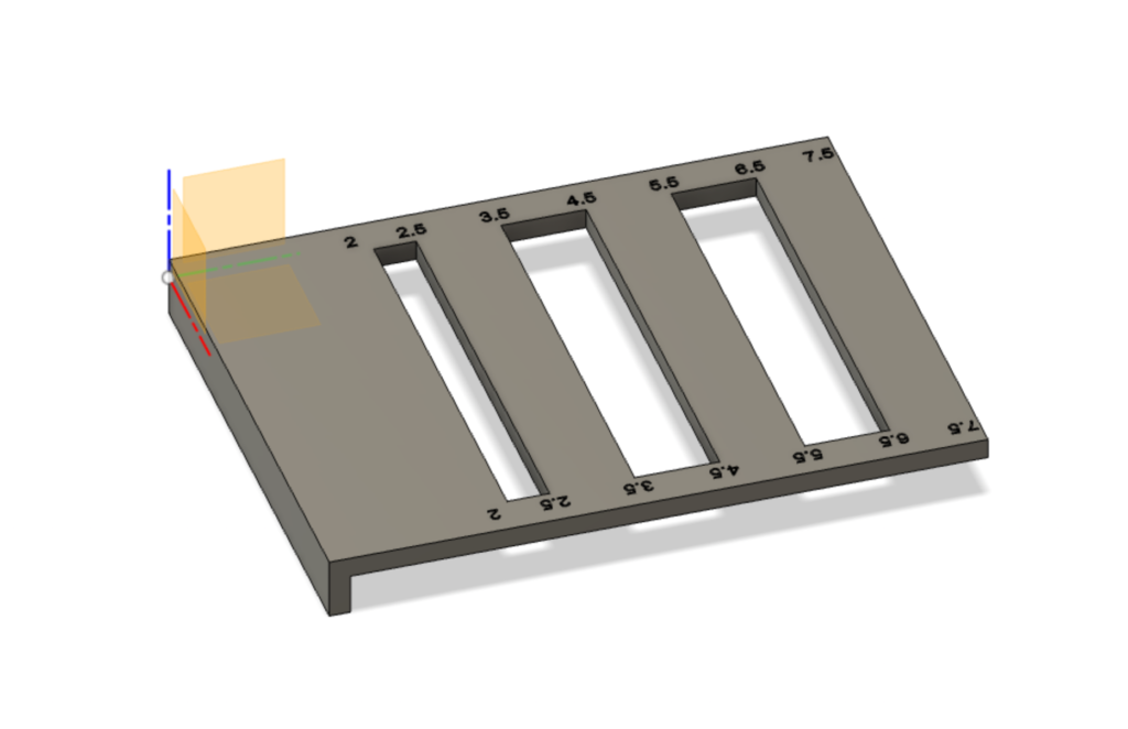
Download all the files for free over on Corbin’s Workshop: Borneman Layout Guide
I’ve been fascinated with timber framing for a few years. This is when you use lots of big pieces of wood, called timers, and traditional woodworking joinery, such as the mortise and tenon. It fell out of style a while ago, particularly in the United States when stick framing took off with relatively unskilled labor that could be used to make houses with smaller wood pieces, typically 2×4’s. You can get a lot more 2x4s out of a log compared to an 8×8.
You have to cut a lot of joinery, and a guy named Al Borneman made a cool little layout square to make it easier to layout some standard size cuts. It is called the “Borneman Layout Template” or “Big Al” or “Borneman Square”. I learned about it by reading Learn To Timber Frame by Will Beemer. I did some internet searching, and realized they were no longer available. Timber Frame HQ made an improved version but it is no longer available. It was also expensive…apparently around $180 – $200.
I decided to quickly make my own based on the pictures I saw in Learn to Timber Frame. I 3D printed it, and it worked out great! One of the hard part of 3D printing is getting overhangs; I decided to only print one side of the guide…and I could make another for the other half. So…a few bucks for this plastic jig, assuming you have a 3D printer. I’m sharing the file for free for others to print their own. A big thanks to Al Borneman!
Currently in the Fusion 360 file, I suppressed two “features” in the timeline; they are the opposite side of the lip; it is hard to print this feature, so I left it off. It would be awesome to print the whole thing at once, but I worry about the print failing or sagging on the bridges.
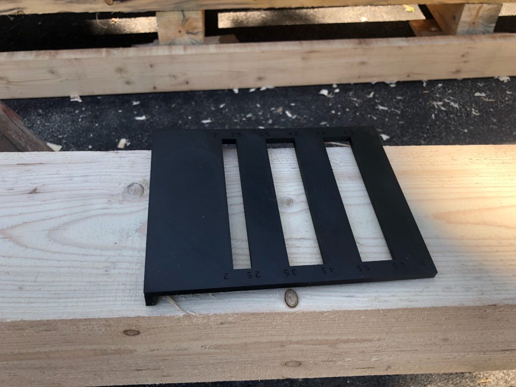
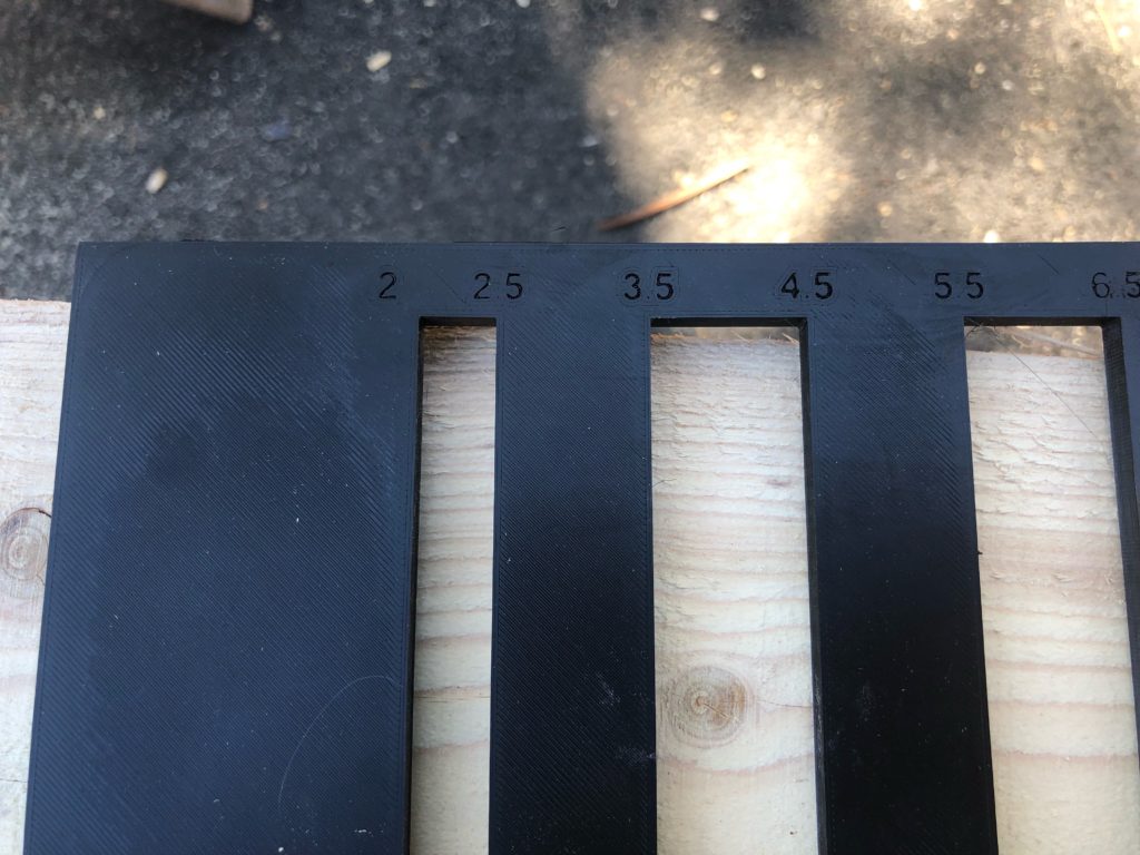


[…] you have a 3D printer, then download the STL that I designed for a Borneman Layout Guide. These are really handy for laying out the lines and joinery. I’d love one in metal, but the […]
I got a quote for 3D printing for the V12.stl version with the overhang on both sides from Xometry. In solid ABS or similar material it would be $90.28 (includes shipping). Pricy but the original metal ones don’t seem to be available anywhere.
Cool – The “v12” one is the complete template with both tabs on the side. The larger one is fatter by 0.5” so the other side can be used for 1/2” increments. Having the tab on the bottom of a print is “difficult” to print with most general fused-filament based printers (called FFF or FDM), so I hope they can successfully print it. It could potentially be printed on its side, but I didn’t try that, and it might have some issues for using pencils on it. I printed the “Large” version which only has the tab on one side. This is easy to print on a home FFF printer by putting the large flat side down. I think I just used PETG to print it and probably 40% infill (might have been less). ABS tends to shrink a little when printed, so consider that. It likely won’t be enough to affect framing layout, but I don’t know for sure.
A resin printer could print the part with really high dimensions and accuracy.
If you do get one, let me know how it comes out!
I got one today from Xometry with the lip on both sides. They did say that there would be some small amount of shrinkage. If this image comes through does this it look right, the The full length is closer to 7.75 inches than 7.5
Looks perfect! the number on top are for measurements from the other side, because you drop it down on your wood and mark it from the top. That back lip on the bottom is 1/4″ thick; it’s thickness doesn’t really matter. The important dimension is from the inside of the back lip to the empty slots. Measure it underneath the jig to the lip; it should be 2″, 2.5″, etc. Flip it over, and it should read 1.5″, 2″, etc (from the fat lip, when it is on the bottom side).
Can you send me the measurements from the edges to the grooves so I can check this
I’m not sure what you are asking – they are the numbers printed on the template. Drop it on a table, draw a line, and measure it with a tape measure. Does it match up to the number on the template?
Ok, it does look ;perfect, now I need to start planning my next timber frame project. I remember this tool being very important in the class I took a few years ago.. Thank you again for supplying the file used for3-D printing.
Awesome, I’m glad it worked out! It’s great that the 3D printing service can do both sides.
I am wondering if you would be interested in making an stl for 3D production of a different template (picture attached) to lay out knee braces on 4 X 6 timber, layout a dovetail, and have a 8 by 2 opening to gauge tenons.
If so, please let me know if my diagram is clear. The angles on the knee brace are 45 degrees. The cross hatch areas are eliminated. The small triangle cross hatch on the long orientation is to establish the line used to cut the 3.5 inch tenon.. The 3/8 inch hold off on the other side is for housing.
That looks complex! It takes a lot of time to do designs; right now i’m a bit busy with other projects. Take a look at Fusion 360; you could learn to sketch out the basic dimensions you made and “extrude” the surface to a specific thickness and have it in a short amount of time. Fusion 360 does have a bit of a learning curve (it is free for a hobby license).
Thanks, OK I’ll try that.
I used Fusion 360 (after viewing a couple of YOUTUBE videos) and designed a template for a dovetail and knee brace for 4″ x 6″ timbers and a 2″ x 8″ hole for gauging tenons. I sent it off to Xometry today and am hopeful that I end up with what I wanted. I appreciate you help with advice on how to do this.
Awesome! I hope it turns out and works well for you.
Tom, would you be so kind to share the file for the dovetail template? Can you email it to me? houseworkideas@gmail.com.
Thank you!
Simeon
The Big AL Borneman layout template is currently available, I sell them.