LED Cyr Wheel: v2: Chips etc
Here’s some of my progress and notes on making my new cyr wheel. This is partially so I can look back and remember what I did if I have to take it apart for some reason.
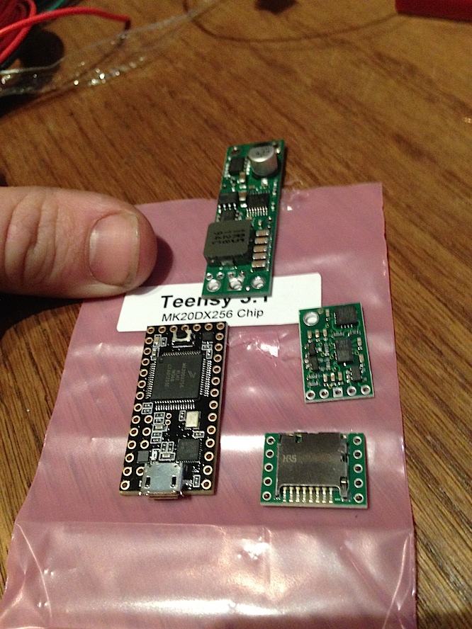
The chips that will go in the wheel: Teensy 3.1 is the main processor (black). Pololu voltage regulator (converts the LiPo 7.4v to 5v for the LEDs and Teensy). Accelerometer/gyro combo (middle right), and SD card reader from the guy who sells the Teensy.
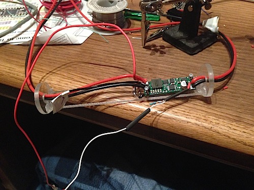
I made a cradle out of acrylic from TAP Plastics. The circles are turned on the lathe and fit perfectly in the wheel. This is the voltage regulator mounted; the wires on the right are flexible (aka: high wire count) 16 gauge wire, which will run throughout the wheel center to deliver 5v. The right side 2 wires will connect to the 7.4v battery, in a different wheel piece. The 2 black/red wires on the left go to the main “5v” feed into the wheel, where each section will tap into (to avoid voltage loss, I’m using 16 gauge…plus, according to my calculations it might need a lot of current to power the wheel). 18 gauge wires are tapped off for the first section LED strips..
Looking at the above picture, the bottom wire is a tap on the source voltage so I can read it with the Teensy. One resistor is already covered in shrink wrap, and the second is the second half of the voltage divider (I forget which side is which; I’d have to look it up). In code, I have:
#define RESISTOR_Z1_VALUE 10000.0 // 10k resistor
#define RESISTOR_Z2_VALUE 4680.0 // MESURED value of 4.7k resistor
static float readBatteryVoltage() {
float readValue = analogRead(g_batteryVoltagePin); // returns 0 – 1023; 0 is 0v, and 1023 is max ref voltage
float vRef = 3.30; // 3.3v ref
float refValue = analogRead(g_batteryRefPin);
float voltageReadValue = readValue / refValue * vRef; // 16 bit resolution,
// The read value is with regards to the input voltage
// See voltage dividor for reference
float voltage = voltageReadValue * (RESISTOR_Z1_VALUE + RESISTOR_Z2_VALUE)/RESISTOR_Z2_VALUE;
return voltage;
}
The white wire feeds into my g_batteryVoltagePin on the teensy.
The above code snippet is how to safely read an arbitrary voltage with a voltage divider. Don’t ever feed a pin more than 5v or you will kill your hardware.
Note that I used two pins..I think I could use some internal ref voltage instead, but I need to look it up more. One tip: to get more stable readings in a Teensy set higher resolution and longer averaging:
analogReadAveraging(16); // longer averaging of reads; drastically stabilizes my battery voltage read compared to the default of 4
analogReadRes(16); // 16 bit analog read resolution
Cradle full
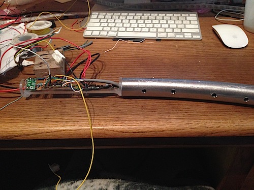
The next picture below shows the cradle with everything on it. The gray wire to the right goes to the SD card reader. The teensy is “sort of” in the middle (slightly biased to the left). On the far left is the accelerometer. Between that and the Teensy is a little board with two 4.7k pull-up resistors for I2C communication with the accelerometer. The teensy needs the resistors. Reference: http://www.pjrc.com/teensy/td_libs_Wire.html
I originally wanted the plastic cradle to be glued to the inert to allow it to easily be pulled in and out. But I wanted the SD card reader to be easily accessible without pulling the whole thing out to change the programmed pattern. So the gray wire goes to the SD reader which floats inside the insert. I wanted it fully on the right side, but I thought it was too much and would interfere with the main plug. So instead, you take the insert out on the left side to change the SD card, and on the right side to plug in the main power. This will make more sense when I take a picture.
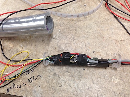
I used some hot glue and screws to hold things in place, and wrapped it a bit to get it to not short out. I will use heat shrink tubing when I know I’m done messing with it.
I should have bought the really flexible “noodle” wire for other parts; it would make sliding the thing in a lot easier. Right now the 18 gauge wire to the LEDs is not very flexible.

